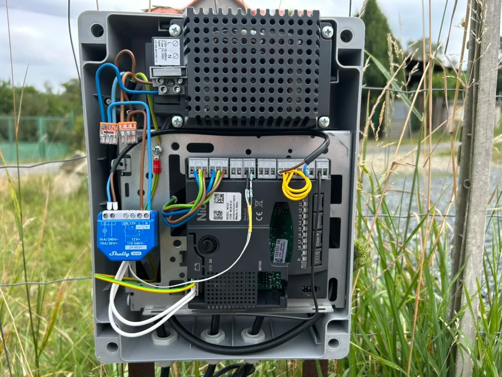
Controlling a Nice Wingo Gate via Home Assistant with Shelly
When I started looking into automating my Nice Wingo gate, the first thing I discovered was that Nice offers a WiFi extension that works out of the box. Great, right? Well, not quite. The problem was twofold: first, it’s costly, and second, I couldn’t find any simple way to integrate it with Home Assistant. For someone who already has their smart home running on Home Assistant, adding yet another app and ecosystem just didn’t make sense.
That’s when I decided to take the DIY route with a Shelly relay. Spoiler alert: it worked beautifully, and I now have full control of my gate through Home Assistant!
The Goal#
What I wanted to achieve was simple:
- Control my Nice Wingo gate through Home Assistant
- Get real-time status updates about whether the gate is open, or closed
Hardware & Software Requirements#
Here’s what I used for this project:
Hardware:
- Nice Wingo gate with MC424R10 control unit (or any compatible control unit with Step-by-Step input and OGI output)
- Shelly 1 Gen4 (any Shelly device with dry contact capability and Add-on compatibility should work)
- Shelly Plus Add-on (for reading the gate status)
- Resistors for voltage divider: 3x 12kΩ (or any similar values, I used what I had on hand)
- Basic electrical tools and wire
Software:
- Home Assistant (already set up)
- Shelly firmware (comes pre-installed on the device)
Why Shelly 1 Gen4? I chose the Shelly 1 Gen4, but any Shelly device with these features should work:
- Dry contact (potential-free) relay output, ideal for connecting to gate control terminals
- Support for the Shelly Add-on, which gives us additional input capabilities
- Scripting capabilities for processing complex signals
How It Works: The Technical Approach#
The integration works in two parts:
Part 1: Controlling the Gate The Shelly’s dry contact relay connects to the Nice control unit’s “Step-by-Step” terminal. This terminal is designed for connecting a momentary wall button that controls the gate in a cycle: Open → Stop → Close → Stop.
Part 2: Reading the Gate State This was the tricky part. Since I only connected the Shelly relay for control, there was no feedback about the gate’s actual position. Here’s where things got interesting.
The Nice control unit has an output called OGI (Open Gate Indicator). On my MC424R10, it’s on terminals 3-4. By default, this output is configured to control an electric lock, but it can be reconfigured to serve as a status indicator. This output is designed for indicator lights and outputs 24V AC (typically in the range of approximately 24-33V).
The problem? The Shelly Add-on’s digital input can only handle up to 15V. The solution? A voltage divider!
The Voltage Divider Solution#
The Shelly Plus Add-on has a digital input with these specifications:
- Voltage range: -15V to +15V maximum
- Logic levels: -15V to 0.5V (True/Logic High) / 2.5V to 15V (False/Logic Low)
- Input impedance: Approximately 14kΩ
To safely connect the Nice OGI output (24-33V) to the Shelly Add-on, I used a voltage divider circuit with:
- R1: 24kΩ
- R2: 12kΩ
   Nice OGI (24-33V) ------+
                           |
                       [R1 24kΩ]
                           |
                           +---------------------- DIGITAL IN
                           |
                       [R2 12kΩ]                   (Internal restance RI≈14kΩ)
                           |
   GND --------------------+---------------------- GND
Voltage at the Shelly Add-on input can be calculated as:
V_out = V_in × (RB / (RB + RT))
Where:
RT = R1 = 24kΩRB = R2 x RI / (R2 + RI) = 12kΩ × 14kΩ / (12kΩ + 14kΩ) ≈ 6.5kΩ
At maximum input voltage (33V):
V_out = 33V × (6.5kΩ / (6.5kΩ + 24kΩ)) = 33V × (6.5kΩ / 30.5kΩ) ≈ 33V × 0.213 ≈ 7V✅
This brings the voltage safely within the 15V maximum specification of the Shelly Add-on.
Processing the OGI Signal#
The OGI output doesn’t just provide a simple on/off signal—it flashes in different patterns to indicate the gate state:
- Fast flashing: Gate is closing (~400ms period raising edge to raising edge)
- Slow flashing: Gate is opening (~1000ms period raising edge to raising edge)
- Solid on: Gate is open
- Off: Gate is closed or in sleep mode
To interpret these flashing patterns, I needed to create a Shelly Script (more on this in the implementation section).
Step-by-Step Installation#
Safety First! ⚠️
Before starting any work:
- Disconnect all power to the gate control unit
- Verify there’s no voltage using a multimeter
- Work carefully with 230V AC mains power
- If you’re not comfortable with electrical work, hire a licensed electrician
Step 1: Reconfigure the Nice Control Unit#
First, we need to change the OGI output from electric lock mode to indicator mode. The exact procedure may vary slightly depending on your Nice control unit model, but the general principle is the same.
For the Nice MC424R10 (and similar models):
- Enter the first-level programming mode by pressing and holding the [Stop/Set] button until LED L1 starts blinking
- Press [Open 🔼] or [Close 🔽] to navigate to LED L5 (Electric lock/OGI function)
- Press [Stop/Set] to toggle the function:
- Short blink = OFF (Electric lock mode)
- Long blink = ON (OGI indicator mode) ← We want this
- Wait 10 seconds for the settings to save
Note: Consult your specific Nice control unit manual for the exact programming procedure. Look for the section about OGI (Open Gate Indicator) configuration.
Step 2: Wire Your Shelly Device to the Gate Controller#
Here’s the complete wiring diagram showing all connections:
                    MAINS POWER (240V AC)
                        |  |
                        |  |
                    +---|--|--+----------+
                    |   L  N  |          |
                    |         |          |
                    |  SHELLY |  ADD-ON  |
                    |  DEVICE |          |
                    |         |          |
    Dry Contact --> |  O   1  | GND  DIN | <- Digital Input from Voltage Divider
                    +--|---|--+--|----|--+
                       |   |     |    |
                       |   |     |    +---+
                       |   |     |        |
                       |   |     +-[12kΩ]-+-[24kΩ]-+ <-- Voltage Divider
                       |   |     |                 |
    NICE CONTROL UNIT  |   |     |                 |
    +------------------+---+-----+-----------------+-----------+
    |                  |   |     |                 |           |
    |  Terminal 12 ----+   |     |                 |           |
    |  (SbS Input)         |     |                 |           |
    |  Terminal 8  --------+     |                 |           |
    |                            |                 |           |
    |  Terminal 3  --------------+                 |           |
    |  (OGI Output 24V)                            |           |
    |  Terminal 4 (GND) ---------------------------+           |
    |                                                          |
    +----------------------------------------------------------+
Note: For MC424R10, terminals are as shown. For other Nice control unit models, refer to your manual for correct terminal numbers.
Components needed:
- 1x 12kΩ resistor
- 2x 12kΩ resistors (to create 24kΩ total when connected in series)
- Shelly Plus Add-on
Step-by-step assembly:
-
Mount Shelly Add-on:
- Mount Add-on on Shelly device
-
Mains power to Shelly:
- Connect 240V AC Live (L) to Shelly L terminal
- Connect 240V AC Neutral (N) to Shelly N terminal
- Follow all local electrical codes
-
Shelly relay to Nice Step-by-Step:
- Connect Shelly output O1 to Nice terminal 12 (Step-by-Step input)
- Connect Shelly output O2 to Nice terminal 8 (Common 24V)
-
Build & connect voltage divider:
- Solder two 12kΩ resistors in series to create 24kΩ
- Connect 24kΩ resistor to Nice terminal 3 (OGI output)
- Connect 12kΩ resistor string to Nice terminal 4 (GND)
- At the junction between the resistors, connect to Shelly Add-on DIGITAL IN
- Connect Nice terminal 4 (GND) to Shelly Add-on GND
Step 3: Configure the Shelly Device#
Initial Setup:
- Power up your Shelly device
- Connect to the Shelly’s WiFi access point from your phone (usually named “shelly…” followed by device ID)
- Configure WiFi settings to connect to your home network
- Note the IP address assigned to the device
Configuring the Relay:
- Open a web browser and navigate to the Shelly’s IP address
- Go to Settings → Output Configuration
- Set the relay to “Momentary” mode and action on power on to “Turn OFF”
- In Automations -> Timers section, set Auto OFF timer to 0.5s (this simulates a button press)
Step 4: Create the Shelly Script for Gate Status#
This is where the magic happens! We need a script running on the Shelly that interprets the flashing OGI signal and translates it into gate states.
Create a Virtual Component:
- In the Shelly web interface, go to Settings → Virtual Components
- Create a new Enum component named “gate_status” with possible values:
openclosedopeningclosing
Create the Script:
Go to Scripts → Add Script and paste the following script:
// Nice Wingo Gate Status Monitor for Shelly with Home Assistant Integration
//
// OGI (Open Gate Indicator) is the ONLY input - a light signal from the gate controller
// OGI behavior:
//   - Flashes slowly (~1003ms period) = gate is OPENING
//   - Flashes fast (~403ms period) = gate is CLOSING
//   - Steady ON = gate is OPEN
//   - Steady OFF = gate is CLOSED (or sleep mode if was previously OPEN)
//   - After 60 seconds of being open, OGI goes to sleep (OFF) but gate remains open
//
// State transitions: closed -> opening -> open -> closing -> closed

let CONFIG = {
  inputId: 100,            // Binary input ID connected to OGI port
  virtualEnumId: 200,      // Virtual enum component ID to update
  slowFlashMin: 850,       // Minimum slow flash period (ms) - opening
  slowFlashMax: 1150,      // Maximum slow flash period (ms) - opening
  fastFlashMax: 550,       // Maximum fast flash period (ms) - closing
  stableTime: 1500,        // Time to confirm stable state (ms)
  flashCountMin: 2         // Minimum flashes to confirm flashing state
};

let state = {
  ogiValue: null,              // Current OGI input state (true=ON, false=OFF)
  lastPositiveEdgeTime: 0,     // Timestamp of last OGI rising edge
  flashPeriods: [],            // Array of flash periods (time between rising edges)
  gateState: null,             // Current gate state: opening/open/closing/closed
  stableTimer: null            // Timer handle for detecting when flashing stops
};

// Get handle to virtual enum component
let virtualEnum = Virtual.getHandle("enum:" + CONFIG.virtualEnumId);

// Initialize
function init() {
  if (virtualEnum) {
    virtualEnum.setValue("closed");
    state.gateState = "closed";
    print("Gate monitor initialized, state: closed");
  } else {
    print("ERROR: Virtual enum component not found!");
  }
}

// Update gate state
function setGateState(newState) {
  if (state.gateState !== newState) {
    print("Gate state:", state.gateState, "->", newState);
    state.gateState = newState;

    if (virtualEnum) {
      virtualEnum.setValue(newState);
    }
  }
}

// Calculate average flash period from collected data
function getAverageFlashPeriod() {
  if (state.flashPeriods.length === 0) return 0;

  let sum = 0;
  for (let i = 0; i < state.flashPeriods.length; i++) {
    sum += state.flashPeriods[i];
  }
  return sum / state.flashPeriods.length;
}

// Analyze collected flash data and determine what the flashing means
function analyzeFlashPattern() {
  if (state.flashPeriods.length < CONFIG.flashCountMin) {
    return null;  // Not enough data
  }

  let avgPeriod = getAverageFlashPeriod();

  // Slow flash = opening
  if (avgPeriod >= CONFIG.slowFlashMin && avgPeriod <= CONFIG.slowFlashMax) {
    return "opening";
  }

  // Fast flash = closing
  if (avgPeriod <= CONFIG.fastFlashMax) {
    return "closing";
  }

  return null;  // Unknown pattern
}

// Called when OGI stops changing (becomes stable)
function onOgiStable() {
  print("OGI stable detected");

  let flashPattern = analyzeFlashPattern();

  // Case 1: We detected flashing that has now stopped
  if (flashPattern !== null) {
    print("Flash pattern:", flashPattern, "avg:", getAverageFlashPeriod().toFixed(1) + "ms", "OGI:", state.ogiValue ? "ON" : "OFF");

    // Opening flash stopped -> gate should be open (validate OGI is ON)
    if (flashPattern === "opening") {
      if (state.ogiValue === true) {
        setGateState("open");
      } else {
        print("WARNING: Opening flash detected but OGI is OFF - keeping 'opening' state");
        setGateState("opening");
      }
    }
    // Closing flash stopped -> gate should be closed (validate OGI is OFF)
    else if (flashPattern === "closing") {
      if (state.ogiValue === false) {
        setGateState("closed");
      } else {
        // OGI is still ON after closing flash: stable timer caught us mid-pulse.
        // Re-arm the timer so we check again once OGI settles, even if no further
        // edges arrive (without this re-arm the state would be stuck at "closing").
        print("WARNING: Closing flash detected but OGI is ON - scheduling recheck");
        state.stableTimer = Timer.set(CONFIG.stableTime, false, onOgiStable);
      }
    }

    // Clear flash data for next cycle
    state.flashPeriods = [];
    return;
  }

  // Case 2: No flashing detected, OGI just changed to stable state
  // This happens after device reboot, or when OGI goes to sleep
  print("No flash pattern, OGI is:", state.ogiValue ? "ON" : "OFF");

  // Handle transitional states without flash data
  if (state.gateState === "opening") {
    setGateState("open");
    return;
  }

  if (state.gateState === "closing") {
    setGateState("closed");
    return;
  }

  // OGI steady ON = gate is open
  if (state.ogiValue === true) {
    setGateState("open");
    return;
  }

  // OGI steady OFF = could be closed OR sleep mode
  if (state.ogiValue === false) {
    // If gate was open, this is sleep mode - stay open
    if (state.gateState === "open") {
      print("Sleep mode detected - gate stays open");
      return;
    }
    // Otherwise gate is closed
    setGateState("closed");
    return;
  }
}

// OGI input changed
function onOgiChange(event) {
  let newOgiValue = event.info.state;
  let now = Date.now();

  // Initialize on first event
  if (state.ogiValue === null) {
    state.ogiValue = newOgiValue;
    state.lastPositiveEdgeTime = newOgiValue ? now : 0;
    return;
  }

  // Detect rising edge (OFF -> ON) and measure flash period
  if (newOgiValue === true && state.ogiValue === false) {

    // If we have a previous rising edge, calculate period
    if (state.lastPositiveEdgeTime > 0) {
      let period = now - state.lastPositiveEdgeTime;

      // Valid flash period (50ms - 2000ms)
      if (period > 50 && period < 2000) {
        state.flashPeriods.push(period);

        // Keep only last 10 periods
        if (state.flashPeriods.length > 10) {
          state.flashPeriods = state.flashPeriods.slice(1);
        }

        print("Flash period:", period + "ms", "(count:", state.flashPeriods.length + ")");

        // Once we have enough flashes, immediately recognize the pattern
        if (state.flashPeriods.length >= CONFIG.flashCountMin) {
          let pattern = analyzeFlashPattern();

          if (pattern === "opening") {
            print("Opening pattern recognized! avg:", getAverageFlashPeriod().toFixed(1) + "ms");
            setGateState("opening");
          }
          else if (pattern === "closing") {
            // Guard: residual pulses after the gate finishes closing (OGI noise)
            // can look identical to a closing pattern. Never re-enter "closing"
            // from "closed" state — wait for onOgiStable to make that call.
            if (state.gateState !== "closed") {
              print("Closing pattern recognized! avg:", getAverageFlashPeriod().toFixed(1) + "ms");
              setGateState("closing");
            }
          }
        }
      }
    }

    state.lastPositiveEdgeTime = now;
  }

  // Update OGI value
  state.ogiValue = newOgiValue;

  // Restart stable timer - fires when OGI stops changing
  if (state.stableTimer !== null) {
    Timer.clear(state.stableTimer);
  }
  state.stableTimer = Timer.set(CONFIG.stableTime, false, onOgiStable);
}

// Register event handler
Shelly.addEventHandler(function(event) {
  if (event.component === "input:" + CONFIG.inputId && event.info) {
    onOgiChange(event);
  }
});

// Startup
print("=== Nice Wingo Gate Monitor ===");
print("OGI Input: input:" + CONFIG.inputId);
print("Opening flash: ~1003ms, Closing flash: ~403ms");
print("Monitoring OGI signal...");

init();

// Get initial OGI state
let initialStatus = Shelly.getComponentStatus("input:" + CONFIG.inputId);
if (initialStatus) {
  state.ogiValue = initialStatus.state;
  state.lastPositiveEdgeTime = initialStatus.state ? Date.now() : 0;
  print("Initial OGI:", initialStatus.state ? "ON" : "OFF");
}
What this script does:
- Monitors the digital input from the Shelly Add-on
- Detects flash patterns:
- Slow flashing (850-1150ms) = Gate is opening
- Fast flashing (<550ms) = Gate is closing
- Determines gate state based on flash frequency:
- After 2 flashes in a pattern, immediately updates to “opening” or “closing”
- When flashing stops, transitions to final state (“open” or “closed”)
- Handles OGI sleep mode: After 60 seconds of inactivity, the OGI output turns off to save power. The script remembers the previous state and correctly maintains “open” status even when OGI is off due to sleep mode.
- Updates the virtual enum component which Home Assistant can read
Important Configuration:
In the script, make sure these values match your Shelly setup:
inputId: 100- This should match the ID of your Shelly Add-on digital input (check in your Shelly web interface)virtualEnumId: 200- This should match the ID of your virtual enum component
To find these IDs:
- Go to your Shelly web interface
- Navigate to Components
- Find your Add-on input and virtual enum component
- Note their IDs and update the CONFIG section accordingly
Enable the Script: After creating the script, enable it so it runs automatically when the Shelly boots up.
Step 5: Integrate with Home Assistant#
Now that the Shelly is configured and exposing the gate status, it’s time to add it to Home Assistant.
Add the Shelly Integration:
- In Home Assistant, go to Settings → Devices & Services
- Click ”+ Add Integration”
- Search for “Shelly” and select it
- Home Assistant should auto-discover your Shelly device
- Follow the prompts to complete the setup
Create a Cover Template:
Add this to your Home Assistant configuration.yaml:
template:
    - cover:
          - name: Gate
            unique_id: cover.gate
            device_class: gate
            state: "{{ states('sensor.gate_status') }}"
            open_cover:
                - action: switch.turn_on
                  target:
                      entity_id: switch.gate
            close_cover:
                - action: switch.turn_on
                  target:
                      entity_id: switch.gate
            stop_cover:
                - action: switch.turn_on
                  target:
                      entity_id: switch.gate
Why this template? Since the Nice Wingo operates in a cycle (Open-Stop-Close-Stop), all three actions (open, close, stop) trigger the same relay. The actual state is determined by reading the sensor value from our virtual enum component.
After adding this configuration:
- Restart Home Assistant
- You should now see a “Gate” entity in your dashboard with proper status indication
Troubleshooting Tips:#
Gate doesn’t respond to commands:
- Check that the Shelly relay is properly connected to the Step-by-Step and Common terminals on the Nice unit (terminals 12 and 8 on MC424R10)
- Verify the relay is configured for momentary/pulse mode (500ms duration)
- Test the relay manually through the Shelly web interface
Status doesn’t update correctly:
- Verify the voltage divider is properly connected
- Check that the OGI function is enabled on the Nice unit (on MC424R10: LED L5 should show long blink)
- Use a multimeter to verify the voltage levels at the Shelly Add-on input
- Review the Shelly script logs for any errors
Flashing patterns not recognized:
- The script needs to be fine-tuned for your specific gate timing
- Use the Shelly logs to observe the actual timing patterns
- Adjust the threshold values in the script if needed
Results#
After completing this integration, you are ready to enjoy full control of your Nice Wingo gate through Home Assistant!
The system has been rock-solid reliable. The status updates are nearly instantaneous, and I love being able to check if I left the gate open from anywhere.
Have questions or want to share your own gate automation project? Drop a comment below!
Disclaimer: Working with mains electricity and gate automation systems can be dangerous. This article is for educational purposes. If you’re not confident in your electrical skills, please consult a licensed electrician. Improper installation could result in property damage, injury, or death.
Comments
Join the discussion! Comments are powered by GitHub Discussions.